
- Published on
AutoCAD Elevation to Render with AI: A Clean 2D Workflow
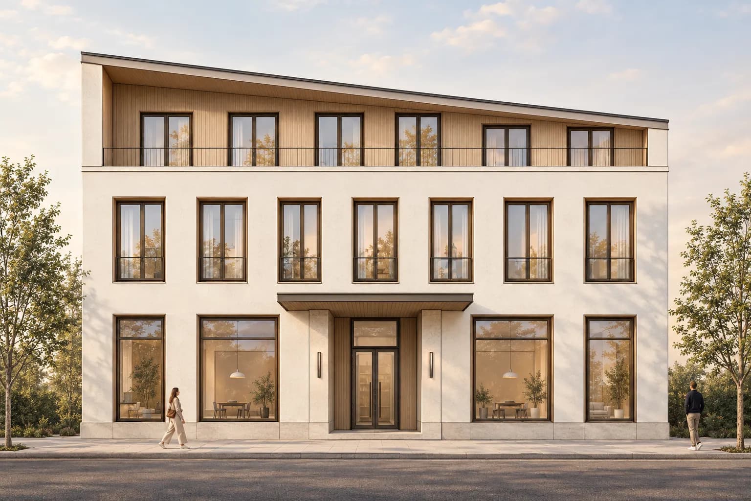
To turn an AutoCAD elevation into a render, isolate the visible facade first. Hide dimensions, grids, notes, dense hatches, and temporary option layers. Keep openings, roof lines, floor edges, entrances, and material boundaries. Export a clean PNG at the final crop. Then use that image in Enhance. Describe the cladding, glazing, ground edge, light, and limited entourage.
A flat elevation can guide a rendered elevation well. It cannot describe depth that the drawing does not show. Recesses, returns, roof depth, and side walls remain inferred. Use a 3D view when those decisions matter. In every case, compare the image with the DWG before client review.
Can an AutoCAD elevation become an AI render?
Yes. A clean 2D elevation can guide a material and light study. The drawing sets the facade outline, openings, floor rhythm, roof profile, and visible edges. The brief supplies the intended finish.
CAD Scene Enhance starts from one source image. It asks the image model to preserve the visible geometry, proportions, framing, and aspect ratio. That instruction is a constraint, not a measured guarantee. Generated details can still drift.
The source also has a hard limit. An elevation does not reveal hidden depth. The model may infer window recesses, wall returns, roof thickness, or the side of a canopy. Check those details against sections, plans, and the DWG.
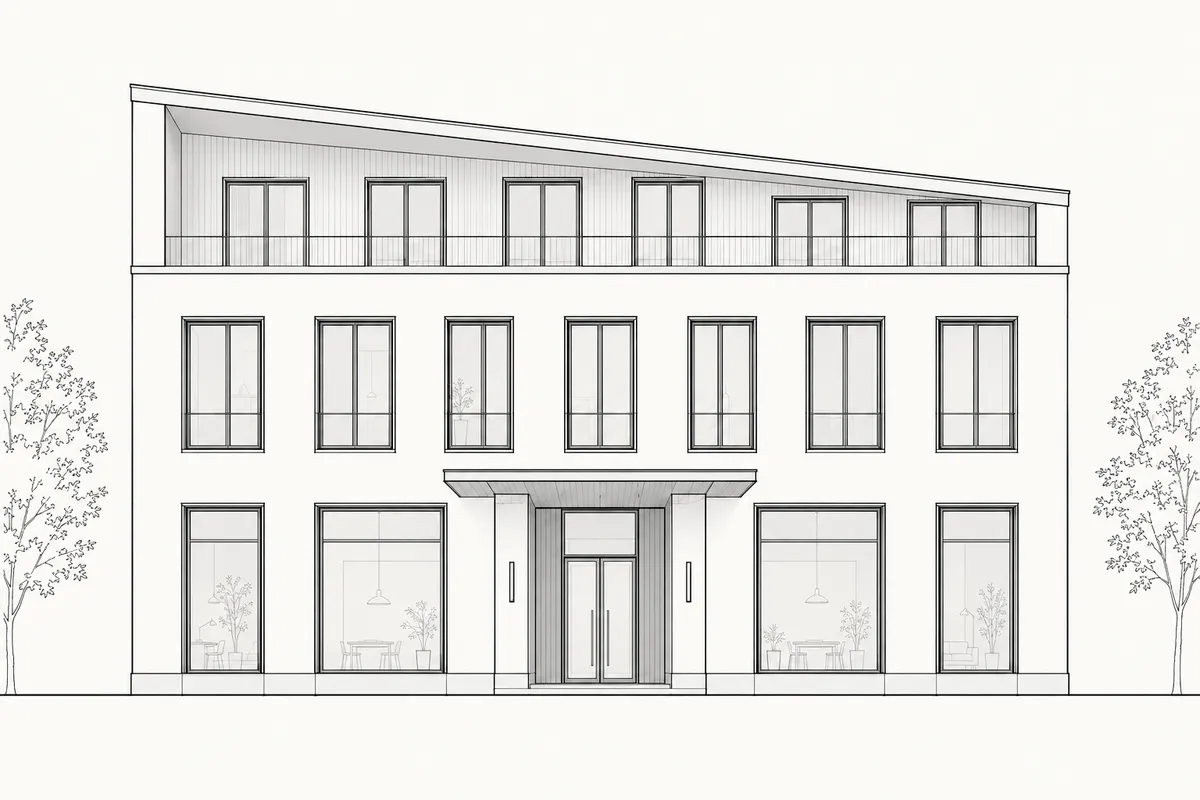 Synthetic elevation
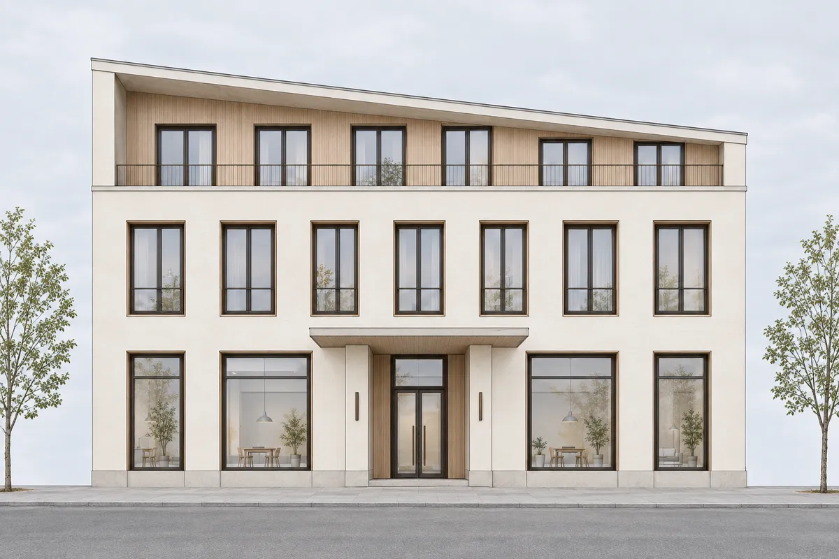 Facade study
The broader screenshot-to-render workflow covers perspective sources from several modeling tools. The AI exterior rendering guide goes deeper into facades, glazing, site, and atmosphere.
Which AutoCAD source should you use?
Choose the source that exposes the decisions under review. A clean elevation fits material, opening, and facade-rhythm studies. A 3D view fits massing, depth, and perspective.
| Source | Best use | Main limit |
|---|---|---|
| Clean 2D elevation | Facade materials, opening rhythm, and color studies | Hidden depth and returns remain inferred |
| Parallel 3D view | Massing, roof depth, side walls, and material transitions | Working layers and construction lines can remain visible |
| Perspective model view | Client-facing exterior atmosphere and eye-level scale | Camera and crop must be fixed before export |
| Plotted layout | A composed crop with controlled lineweights | Dimensions, notes, title blocks, and stamps may leak in |
Use a perspective source when the image must explain spatial depth. AutoCAD can hold 3D geometry, but a 2D elevation cannot recover information that was never drawn. Do not ask the image to invent a credible corner and then treat that corner as design evidence.
How should you clean the AutoCAD elevation?
Prepare a visual source, not a construction sheet. Keep lines that explain the building. Remove graphics that can be mistaken for joints, mullions, paving, or facade relief.
Duplicate the intended view
Protect the working drawing, then frame the elevation at its final aspect ratio.Isolate the facade layers
Keep visible geometry and material boundaries. Hide dimensions, notes, grids, markers, and temporary options.Set deliberate lineweights
Use a clear silhouette and lighter internal detail. Remove dense hatches that obscure openings.Export one clean raster
Save a PNG with the intended crop, contrast, background, and enough pixels for review.Render and compare
Describe finishes and light in Enhance, then compare every opening and edge with the DWG.
AutoCAD 2026 supports layer visibility through on, off, freeze, thaw, and isolate controls. Autodesk documents Home → Layers → Isolate as a way to show selected layers while turning the others off. Use Unisolate after export to restore the prior layer state.
Keep these layers when they help review:
- primary wall, roof, slab, and opening outlines;
- window and door frames;
- entrance, canopy, balcony, and plinth edges;
- major facade joints that belong to the design;
- a restrained ground line and essential context.
Hide these when they do not belong in the image:
- dimensions, leaders, notes, and revision clouds;
- grids, levels, section marks, and elevation symbols;
- title blocks, stamps, keys, and schedules;
- temporary options and consultant overlays;
- dense material hatches that cover the facade.
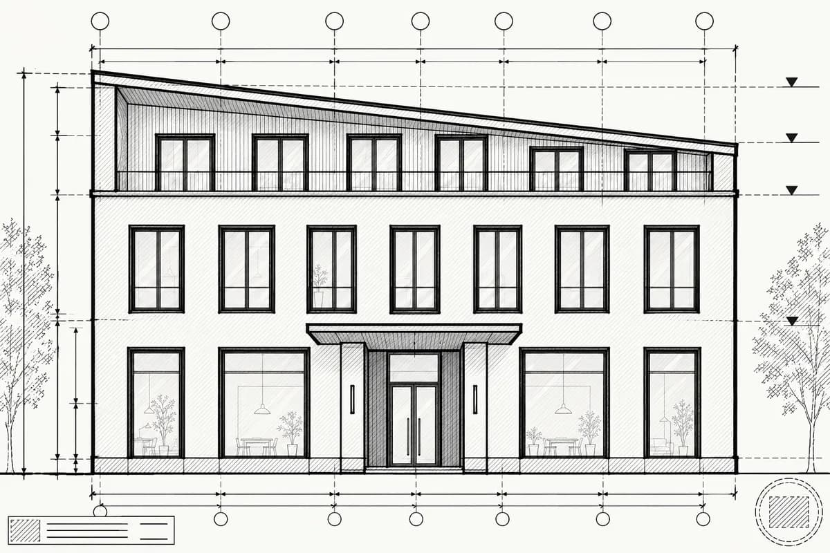
Which lineweights and hatches should stay?
Use lineweight to explain hierarchy. Keep the outer profile and major cut edges clear. Use lighter lines for frames, joints, and background context.
Heavy profiles can become thick trims. Dense hatches can become cladding patterns. Grid bubbles can become signs or lamps. Dimensions can become unreadable text. Remove them unless the article or image intentionally explains documentation.
AutoCAD's Plot and Page Setup dialogs can plot object lineweights and plot styles. Autodesk notes that plot styles can override object properties and automatically include lineweights. Preview the final output rather than trusting the working display.
Keep a simple hatch only when it communicates a real material zone. It should not cover windows, doors, or small edge conditions. The realistic materials guide explains how to review concrete, timber, glass, and their boundaries after rendering.
How do you export a clean image from AutoCAD?
Use PNGOUT when the displayed elevation already has the right crop and objects. Autodesk states that PNGOUT saves selected objects, or all objects and viewports when you press Enter. The file reflects what is displayed. Visible glyphs can also appear, so inspect the source after export.
Use PLOT or EXPORTPDF when a layout and page setup control the crop, scale, and lineweights. AutoCAD 2026 provides general, high-quality print, small-file, and web/mobile PDF presets. A PDF remains a drawing-delivery format. Convert or export the final elevation to a clean raster before using it as the image source.
Check the exported image at full size:
- The facade should fill the frame without clipping.
- Openings and thin frames should remain legible.
- The background should be quiet and uniform.
- No cursor, selection, glyph, note, or plot stamp should remain.
- The pixel dimensions should support the intended screen or board use.
The clean source-image checklist covers crop, edge clarity, overlays, and multi-view review across CAD and 3D tools.
AutoCAD elevation / facade study
Test one clean elevation in CAD Scene.
What should the Enhance brief say?
The source image already carries the visible facade. Ask for materials, light, ground, and scale. Do not ask for a different building.
AutoCAD facade elevation study
Copy the full brief, then adjust one variable at a time.
Prompt
Preserve the exact orthographic view, roof profile, floor lines, entrance, canopy, facade proportions, and every window and door opening. Render warm off-white mineral plaster, pale oak window reveals, dark bronze frames, and a honed limestone plinth. Add restrained street trees and two small people for scale. Use soft late-afternoon daylight. Keep the view straight-on. Do not move openings, add floors, change the roof, or introduce perspective.
Set the Project Composition before sending. Name the Style, Scene, Lighting, Materials, and Entourage required across the study. Use Edit later when one bounded finish or object needs correction.
Avoid vague instructions such as "make it realistic." Name each finish and its location. The architecture render prompt guide shows how to separate subject, materials, light, camera, activity, and constraints.
How can one elevation test several facade directions?
Keep the source, crop, and visible geometry fixed. Change one decision group at a time. Start with material. Then test light. This makes each image easier to compare.
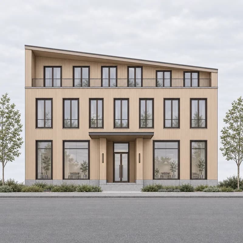
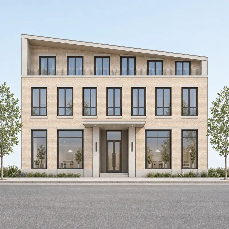
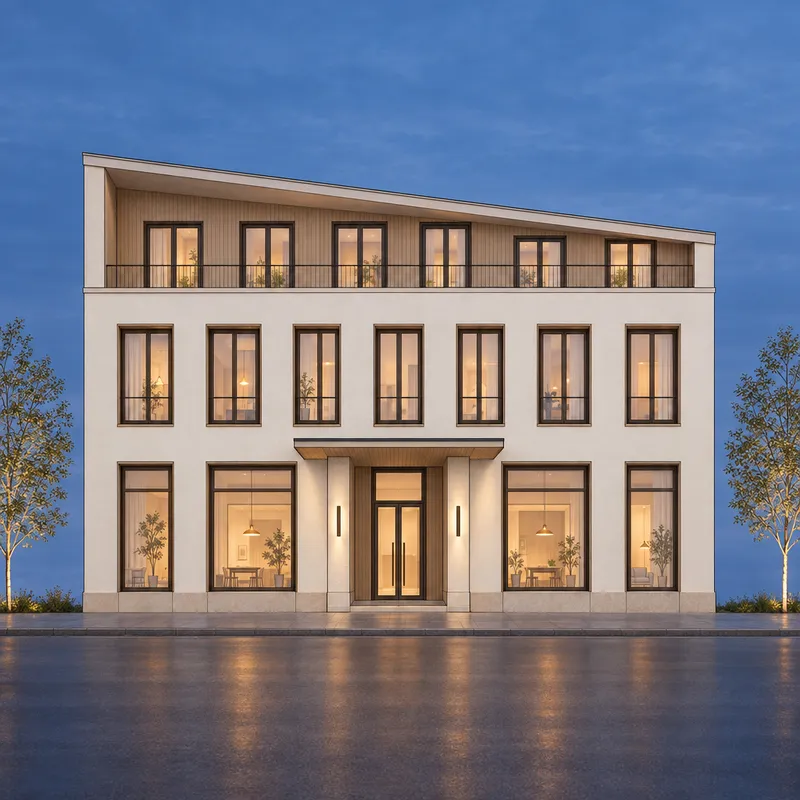
These images share one synthetic elevation lineage. They show a controlled editorial method. They do not prove exact retention or compare rendering models.
What should you check in the finished elevation?
Review the drawing before the atmosphere. Place the exported elevation beside the generated study.
- Trace the roof profile and outer silhouette.
- Count every window and door bay.
- Compare sill, head, parapet, and floor-line positions.
- Check entrance, canopy, balcony, and plinth widths.
- Inspect where each material starts and stops.
- Mark every inferred recess, return, reveal, or roof edge.
- Reject invented signs, fixtures, joints, and extra openings.
Use the render-retention method for a repeatable source check. It defines review criteria. It does not publish a cross-tool benchmark result.
For client review, label the image as a material or light study. Do not present inferred depth as resolved construction. The client render review checklist separates visible decisions from items that still need correction or deferral.
When should you stay in AutoCAD or use a 3D model?
Stay in AutoCAD when the decision depends on dimensions, linework, layer control, exact plotting, or coordinated drawing output. Use a 3D model when the image must explain corners, depth, roof form, shadows, or changing viewpoints.
Use Enhance for quick visual studies from a fixed image. It cannot read the DWG, layers, blocks, object properties, xrefs, dimensions, or plot settings. It cannot update the drawing after an image changes.
The Vectorworks saved-view workflow covers another CAD-led source. The 3ds Max camera workflow fits a modeled perspective. The guide to AI architectural rendering places each source inside the wider Create, Enhance, and Edit workflow.
Sources reviewed
- AutoCAD 2026 PNGOUT command, reviewed 22 September 2026
- AutoCAD 2026 layer visibility and isolation, reviewed 22 September 2026
- AutoCAD 2026 PDF export workflows, reviewed 22 September 2026
- AutoCAD 2026 plotted object options, reviewed 22 September 2026
- CAD Scene Product, Help, prompt guide, and retention method, reviewed 22 September 2026
Questions about AutoCAD elevation rendering
Can CAD Scene open an AutoCAD DWG?
No. Enhance reads an exported image. It does not read the DWG, layers, blocks, xrefs, object properties, dimensions, or plot settings.
Should dimensions and hatches stay visible?
Keep only marks that explain a real visible boundary. Hide dimensions, notes, grids, markers, dense hatches, and plot stamps that could become false image detail.
Can a flat elevation produce a perspective render?
It can inspire one, but hidden depth and side geometry will be inferred. Use a 3D view when corners, roof depth, setbacks, or perspective must remain reviewable.
Will Enhance keep every elevation line exactly?
No exact-retention guarantee applies. The source constrains visible geometry and proportions, but generated details can drift. Compare every important edge and opening with AutoCAD.
Table of Contents
- Can an AutoCAD elevation become an AI render?
- Which AutoCAD source should you use?
- How should you clean the AutoCAD elevation?
- Which lineweights and hatches should stay?
- How do you export a clean image from AutoCAD?
- What should the Enhance brief say?
- How can one elevation test several facade directions?
- What should you check in the finished elevation?
- When should you stay in AutoCAD or use a 3D model?
- Sources reviewed
Authors

- Name
- Vladimir Mindru
Previous Article
Table of Contents
- Can an AutoCAD elevation become an AI render?
- Which AutoCAD source should you use?
- How should you clean the AutoCAD elevation?
- Which lineweights and hatches should stay?
- How do you export a clean image from AutoCAD?
- What should the Enhance brief say?
- How can one elevation test several facade directions?
- What should you check in the finished elevation?
- When should you stay in AutoCAD or use a 3D model?
- Sources reviewed
Authors
- Name
- Vladimir Mindru